| Programming:
Printing Photos in 3D 13th March 2011 One of the 3D printing projects that I've had the most satisfaction from is a Processing sketch to convert 2D photos into a model that can be 3D printed. This isn't a 3D model of what's in the photo, rather it's a way of representing the photo itself with a 3D printed model, I quite liked the idea of a 3D way to print a 2D photo... I describe 2 different techniques in this post and you'll find the source code for the sketches at the end. Halftone The first technique borrows from a standard printing technique - halftone printing. A halftone image uses dots of varying size to create varying brightness in an image. I wanted to make a way to print photos with a halftone pattern made from a 3D printed model, this would allow me to create a hafltone that existed on its own, without paper.
(if you can't see the images, try moving back from your monitor) The first step was to see how I might be able to get information from a photo. This is a task that is really easy to do in Processing. If I create a 'PImage' to store the photo I can then interrogate it to find the brightness in the image pixel by pixel. Once I have the brightness of the pixel I can use it to scale the diameter of a cylinder. Since I am using a white material I can use brightness value directly; a brighter pixel will produce a larger cylinder which in turn will look brighter when the model is printed. To make the cylinders I used a function that I'd developed before to produce a 3D cylinder from point to point in 3D space: void cylinder(float x1, float y1, float z1, float x2, float y2, float z2, float wide, int sides) { This code sets up a transform that allows me to shift a generic cylinder into the position that I want with its ends at the two sets of x, y, z coordinates I supplied in the arguments. An interesting quirk I've found is that this code used to fail when I specified cylinder lengths of less than 1. This was a problem since I wanted to be able to use a cylinder of about 0.8-0.9mm depth. In the end I traced this problem to the PVector "t"; when I tried to use "t.mag()" to get the length of the cylinder it would fail for vectors of less than unit length. I have no idea why and I haven't found any other case where this was a problem, it seems to be specific to this code. Anyway, the float "magmult" is a hack to fix this, all I do is multiply the vector by this value, do what I need to do to get the directions and then remember to divide by the value again later. The cylinder is actually drawn, vertex by vertex, by the function "cyl": void cyl(float cylHeight, float cylRadius, int sides) { [The auto formatting hasn't worked so well for the above, it's the "<" signs in the for loops termination condition that causes the problem] There is another problem with the code above, the order I set up to draw the vertices produces very dodgy normals that have to be fixed in Blender or Meshlab; I accepted this since the fix is a 30 second job and working out the way to fix the initial draw would take longer with no guarantee of success anyway given my coding skills. To write an STL file for 3D printing I've used the excellent unlekker library, all I have to do is have a switch to start the export on a draw() after I press a key ("e" in this case) and then end the export when all the parts have been written. In the end I found that I could only easily get about 30x30 pixels into a model of reasonable price and size, I also found some problems with Shapeways' triangle limit, although I'm not sure that this error is correct based on the polygon count in Blender. The final models are quite effective, even with the low resolution, and I've used quite a few as gifts. This model is available in my Shapeways shop as a co-creator customisable model (I think the guide price of just over €50 is based on the maximum possible volume of the model found with a not-very-interesting all-white image) and I've had some orders from it but I've decided that I will release the code for a few reasons:
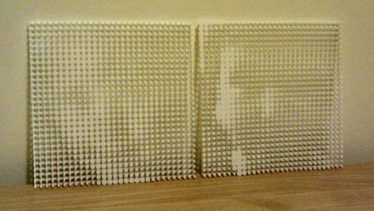
Aperture Grille The second model is based on an aperture grille CRT monitor. Colour CRT monitors use three electron guns to create three separate beams for red, green and blue parts of the final picture. The different colours come from three different phosphors on the front of the picture tube. To control the colours separately each gun must only be able to see one type of phosphor so the other two must be hidden from it. Different monitors use different techniques, shadow masks (metal sheets with holes in them) were common but higher-end monitors sometimes used aperture grilles which were grids of wires oriented vertically, parallel to stripes of phosphor (they also had two horizontal damping wires to keep the grille in alignment: a rather sadistic trick used to be pointing these out to people who hadn't noticed them and watching a good 30% go quietly crazy when they couldn't stop seeing them...) This second model uses a similar principle to the aperture grill monitor to allow me to put two photos in one model. In the same way as I did in the first model I take a photo and interrogate it to get the brightness of each pixel. I then use this to scale a part of the model, in this case the length of a cylinder not the diameter as before. To allow the model to display two photos I interleave two independent sets of 'phosphors', one for each photo. The aperture grille in front then hides one of the sets of cylinders from one angle and the other set when viewed from a different angle. All of these models work best from one or two metres away and the change from one photo to another is quite strange when you see it because you don't see the individual elements of the model from that distance; I've a YouTube video of this happening below: This model doesn't produce images that are as clear as the first one, mainly since the 'pixels' are much smaller and half of what you can see is plain white aperture grille. The model is also much more fragile due to the thin rods it's made of so for both of these reasons I'm not planning to make a co-creator of this one (if enough people mail me I might change my mind but, since you have the code below you can always make your own...) The parts of the source code below that I've written are released under the GNU General Public License, the link will provide details of what this allows you to do. Please note that you don't get a warranty of any kind with this code (see the license terms for more detail); I'm not a professional programmer and so if it doesn't work for you the odds are I won't be able to fix it even if I have time and inclination to try. Processing and the libraries & tools I reference have their own license terms, see their web pages for details. Halftone (zipped PDE files for Processing) Aperture Grille (zipped PDE files for Processing) unlekkerLib library for Processing See the sidebar on the right for links to Processing, Shapeways, Blender, Gimp and other useful things. |
fastness - Iain Banks Graphics

All of the content from my Iain M Banks website, now shifted to be a section in this one
An open source programming tool aimed at artists, engineers and designers. Simple, light and Java-based with a wealth of libraries and a strong user community
Shapeways:
3D printing for the masses - plastics and metal to your design or team up with a desigenr to personalise a design with a 'co-creator'. Visit my Shapeways shop for some things I've designed.
Meshlab:
MeshLab is an open source, portable, and extensible system for the processing and editing of unstructured 3D triangular meshes
Blender:
Blender is the free open source 3D content creation suite, available for all major operating systems under the GNU General Public License
Gimp:
GIMP is the GNU Image Manipulation Program. It is a freely distributed piece of software for such tasks as photo retouching, image composition and image authoring. It works on many operating systems, in many languages
Inkscape:
An Open Source vector graphics editor, with capabilities similar to Illustrator, CorelDraw, or Xara X, using the W3C standard Scalable Vector Graphics (SVG) file format
Ponoko:
Retail laser cutting outlet with centres in New Zealand, USA, Germany, Italy and the UK (if not more by now)
Eclipse:
Java development environment